
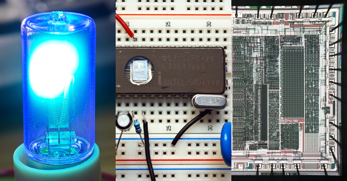
Programming Intel 87C51 - first high-volume integrated microcontroller (1980)
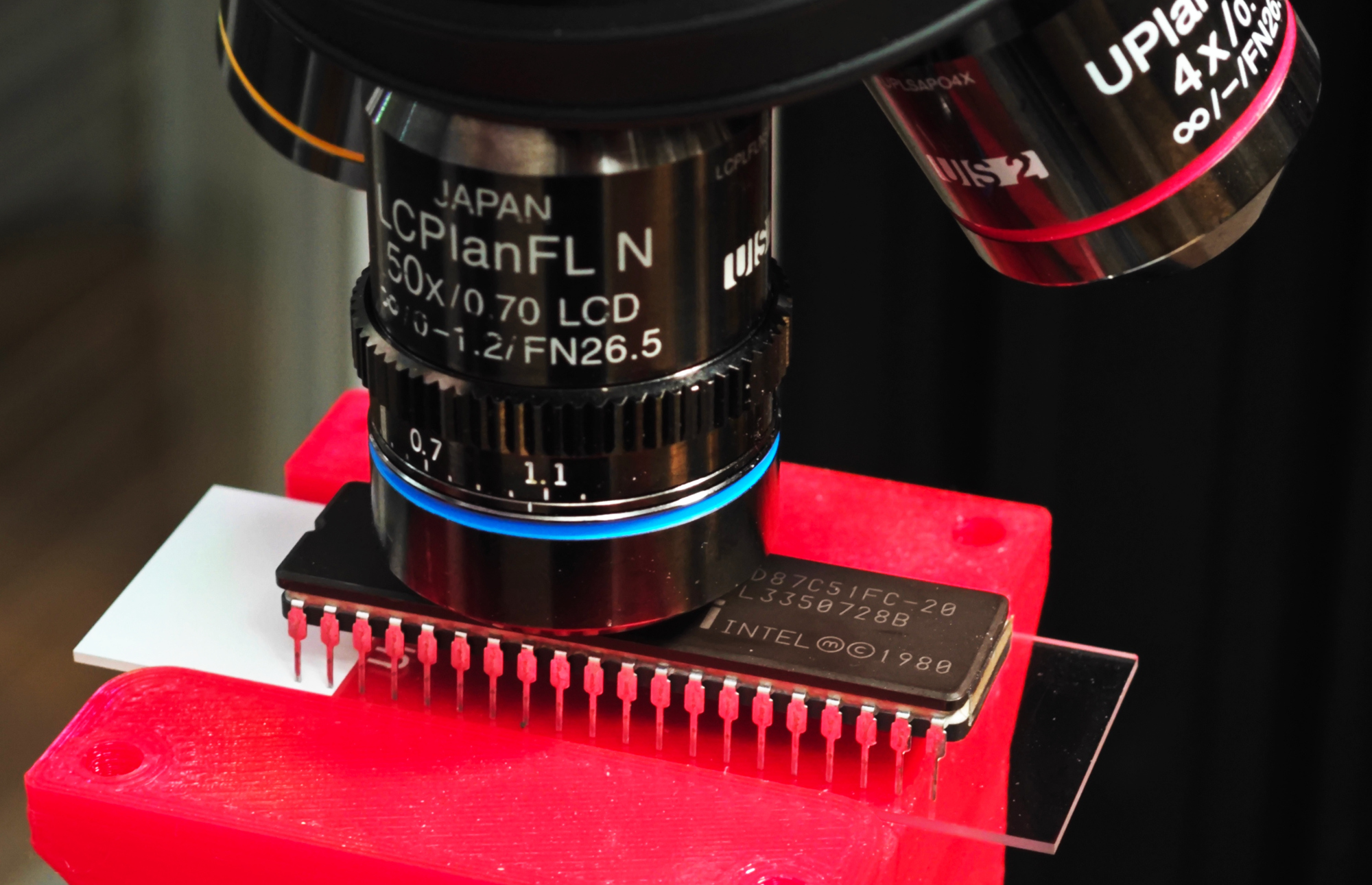
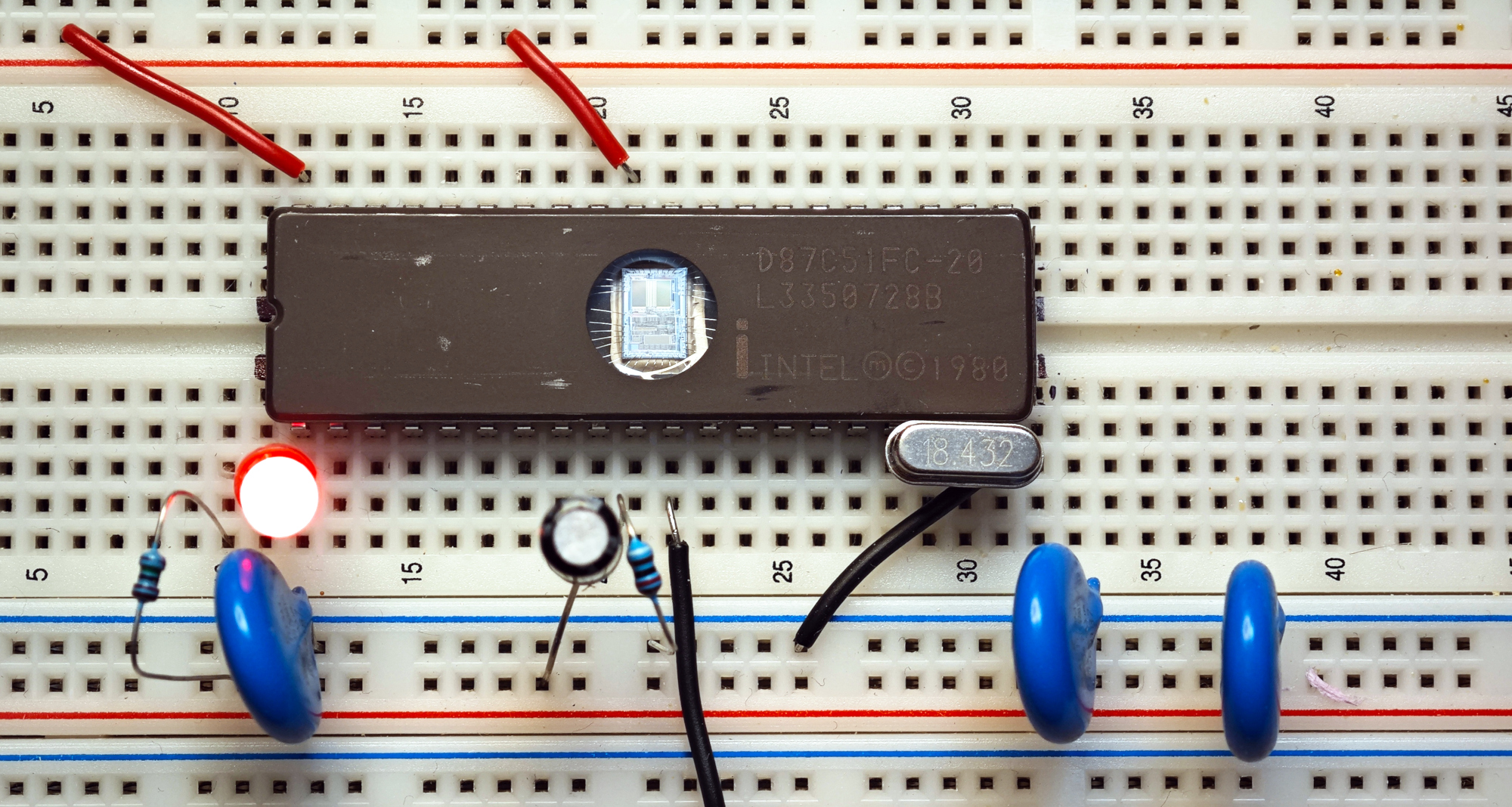
Today we are used to luxury of fully integrated microcontrollers - all key components are conveniently integrated into single reliable part: non-volatile memory, SRAM, CPU core, PLL, ADC/DAC, PWM, serial ports, e.t.c It was not like that in the past and embedded systems typically required lots of chips, until Intel 8048 (MCS-48) was released in 1976 on n-MOS technology. Intel expected that 8048 will have limited product lifetime, and in 4 years, in 1980 it was replaced by 8051 (MCS-51) which conquered the world. It was first high-volume product to integrate 4KiB of PROM, 128 bytes of SRAM, GPIO, serial port as well as 8-bit core in a single crystal. 87C51FC variant was using 32KiB EPROM non-volatile memory instead of PROM's, double SRAM size (256 byte), C-version was manufactured on CMOS process - which makes it exceptionally modern for the time. It was not particularly fast - simplest commands took 12 clock cycles to execute, so even at 20Mhz it was doing just over 1 million operations per second, also - no 16-bit division commands. Modern 8051-compatible cores are much faster and often do single-cycle command execution.Recently I got my hands on D87C51FC-20, and decided to experience the old ways of embedded software.
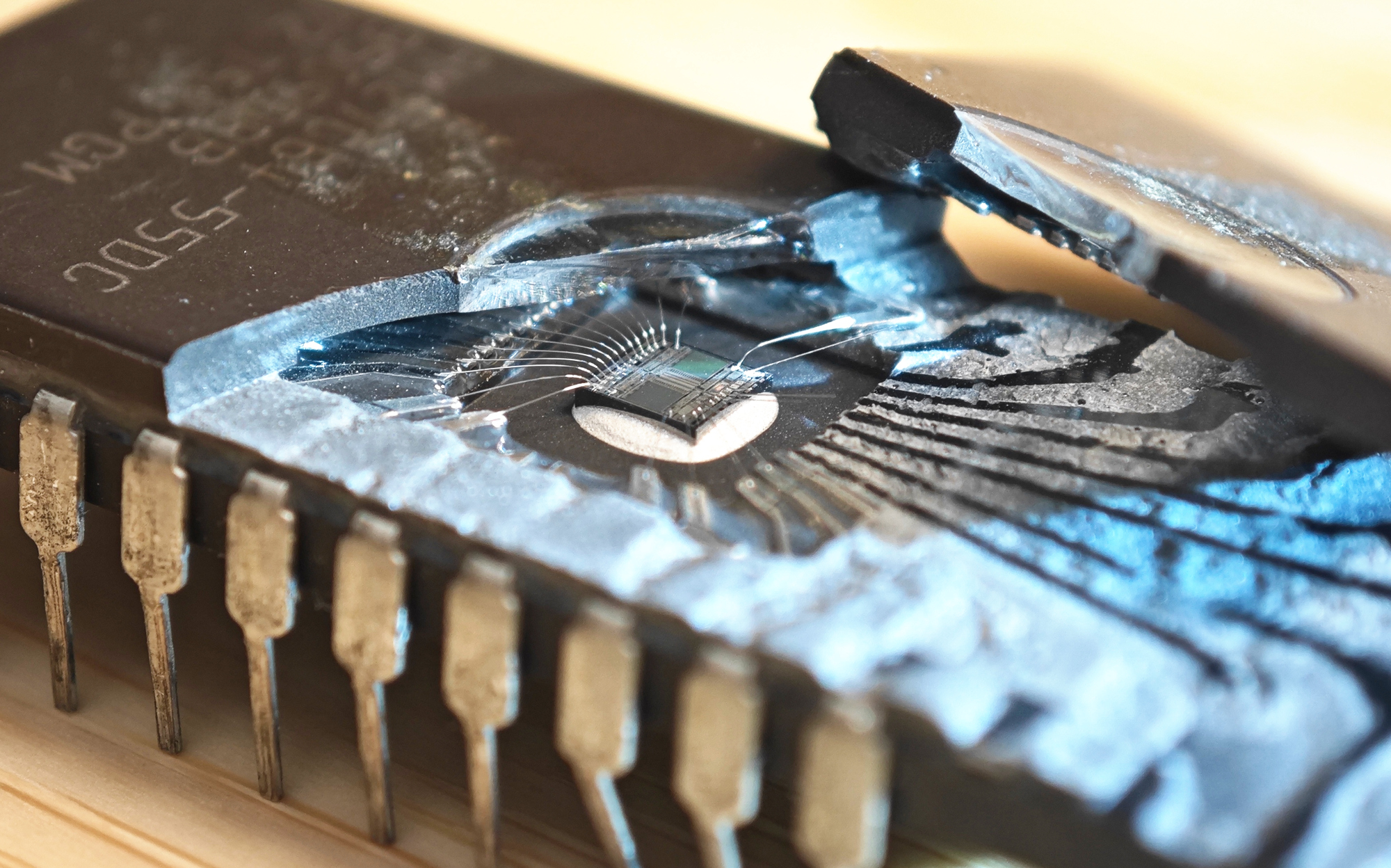
I was curious to see the chip in detail and what is the shape and thickness of the window, so I sacrificed AMD AM27C64. Window thickness appeared to be around 1mm and it was surprisingly well glued into ceramic case:
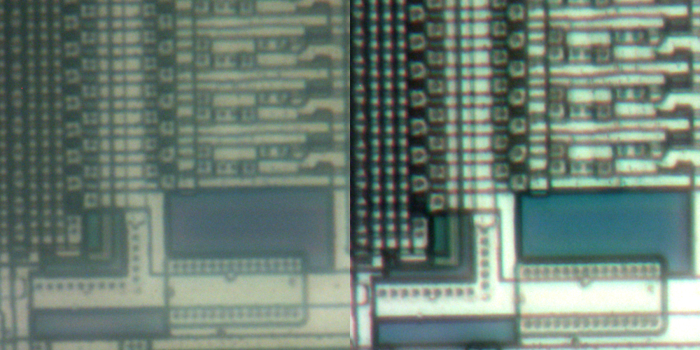
We used to think that flat optical windows do not affect image and we can easily observe things though them. But it is not the case for microscopy imaging with high numerical aperture (i.e. with converging beam), where flat window introduce spherical aberration which severely degrade resolution with lenses not optimized for specific cover glass thickness. Similar problem is with observation of data on CD's - as one increases NA beyond 0.3 - resolution rapidly declines with standard lenses.
Here is an example I've got during observing 87C51. On the left - image without glass thickness correction (low contrast and resolution due to spherical aberration), on the right - with 1.05mm correction:
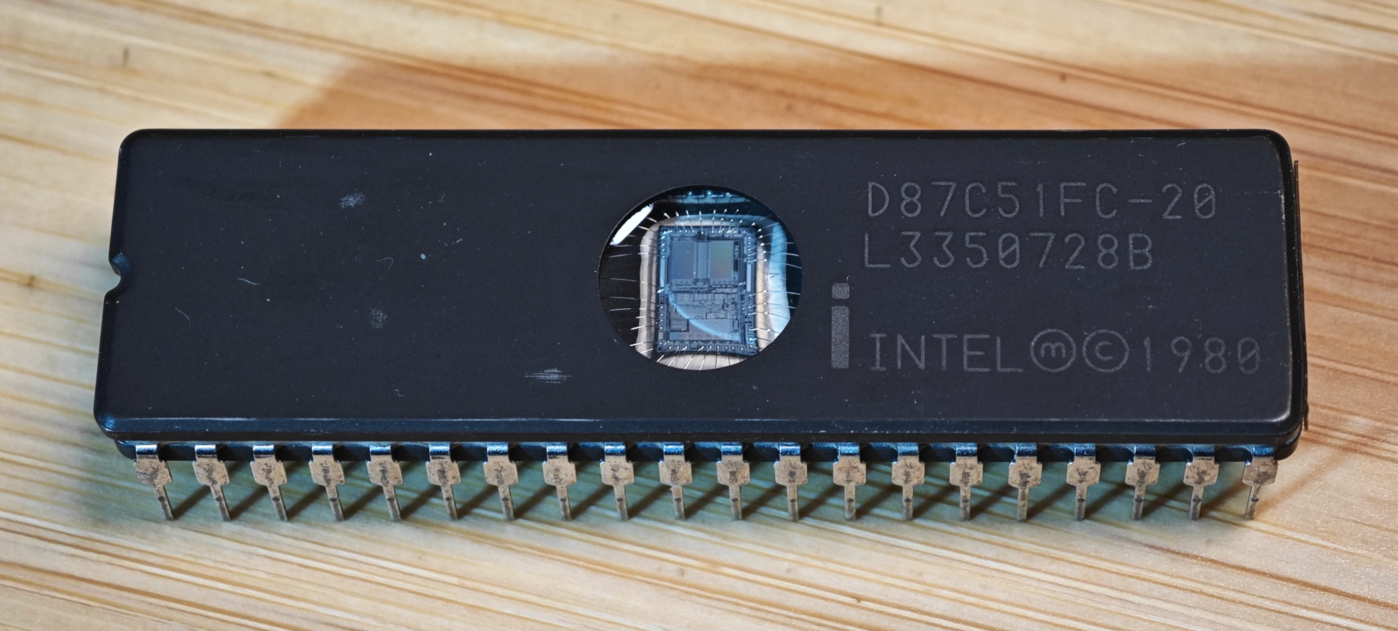
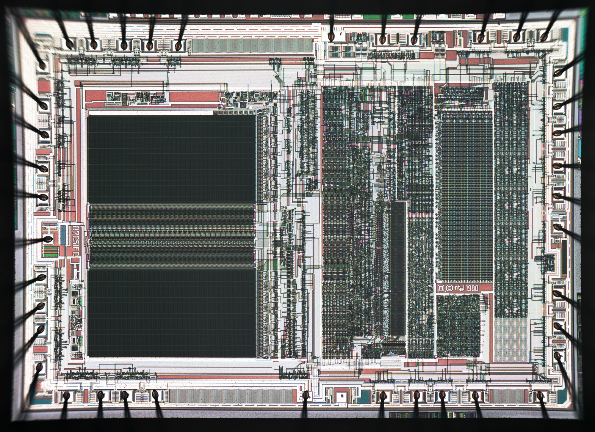
Now we can see the chip itself through quartz window used to erase EPROM content:
UV Erasing
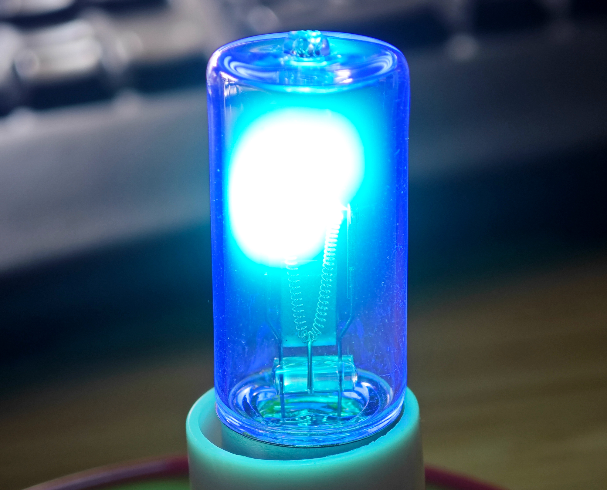
Erasing the chip requires relatively high dose of UV light. I've tried 245nm LED at first, but it's light output was so tiny that even after 1 hour there was no effect. It seems under 350nm mercury-based light sources are unchallenged by semiconductors.Recently I've got these weird 10v/300mA mercury lamps. These exist in "ozone" version (quartz tube, so with 185nm output), and "no-ozone" (some glass that absorb 185nm, but is transparent to 254nm). It is better to use "no-ozone" version, as 254nm became industry standard for EPROM erasing, and 185nm might be too harsh and way less safe. Notice that only upper part of filament is covered by white oxide coating for enhanced electron emission.
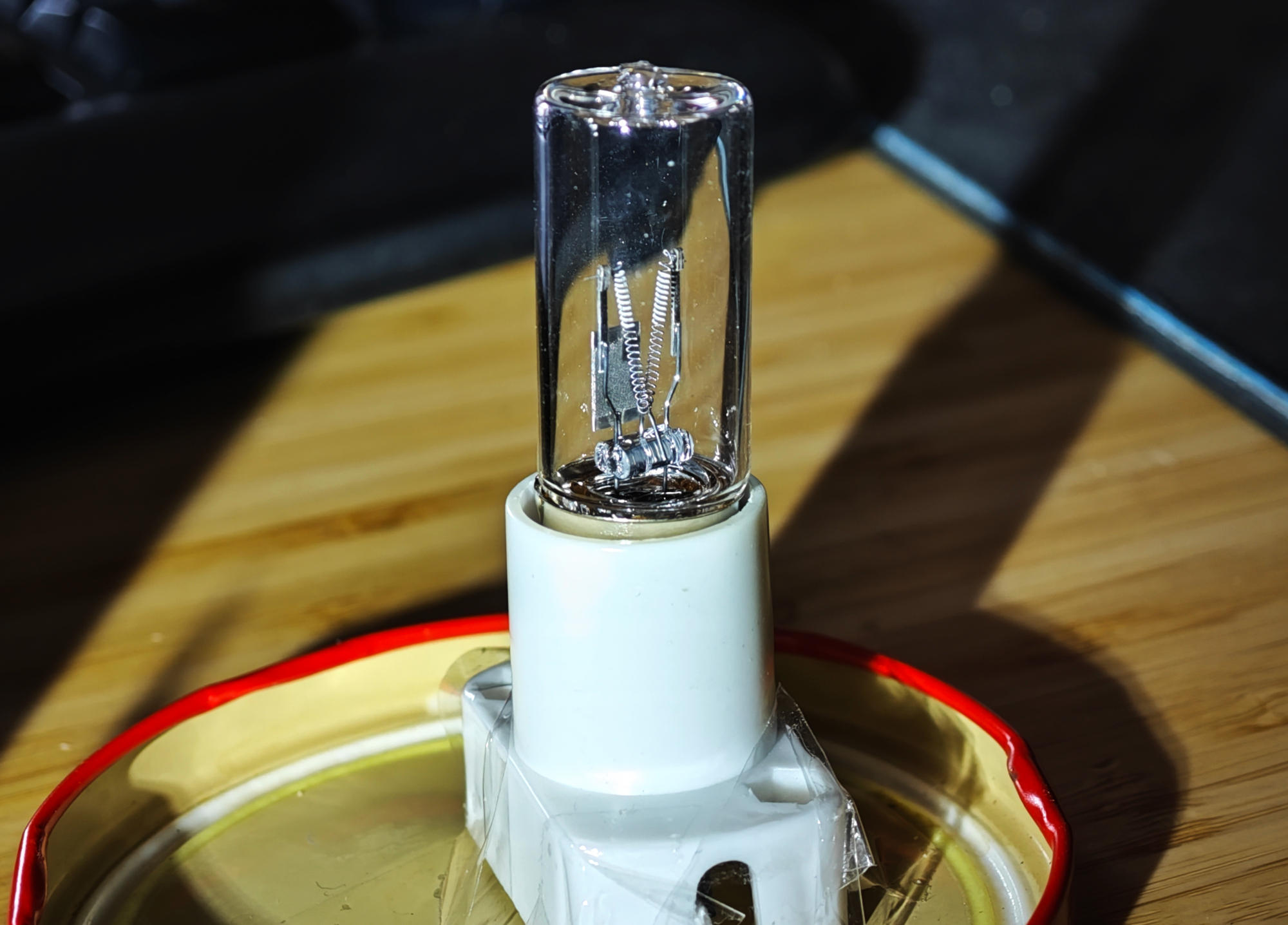
Lamp works in a very unexpected way. Power supply has to be set to ~14-15v with 300mA current limit. Initially filament glows red (especially it's lower part, not covered by oxide) and evaporates mercury from amalgam plate.
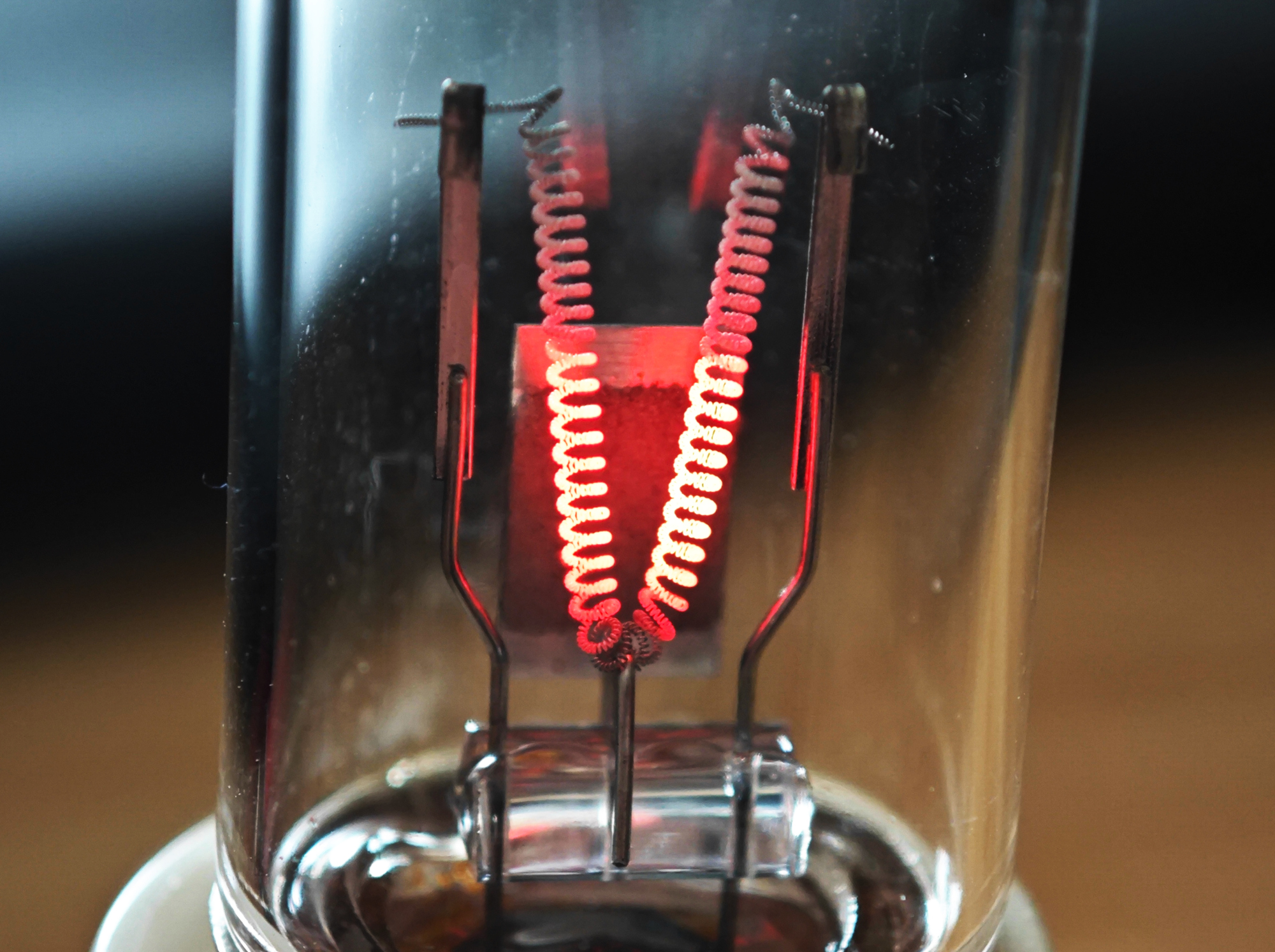
When Mercury vapor pressure is high enough - plasma ignites and shunts filament. Electron emission from warm oxide-coated filament is enough to sustain plasma. This photo was made with protection glasses, and camera with UV filter (as you don't need much 185nm light to damage optical glue/plastic). Needless to say that with 185nm light one need to protect whole body + ozone is toxic. So it's really better to work with no-ozone version.
When quartz glows blue - it's time to drop and run!
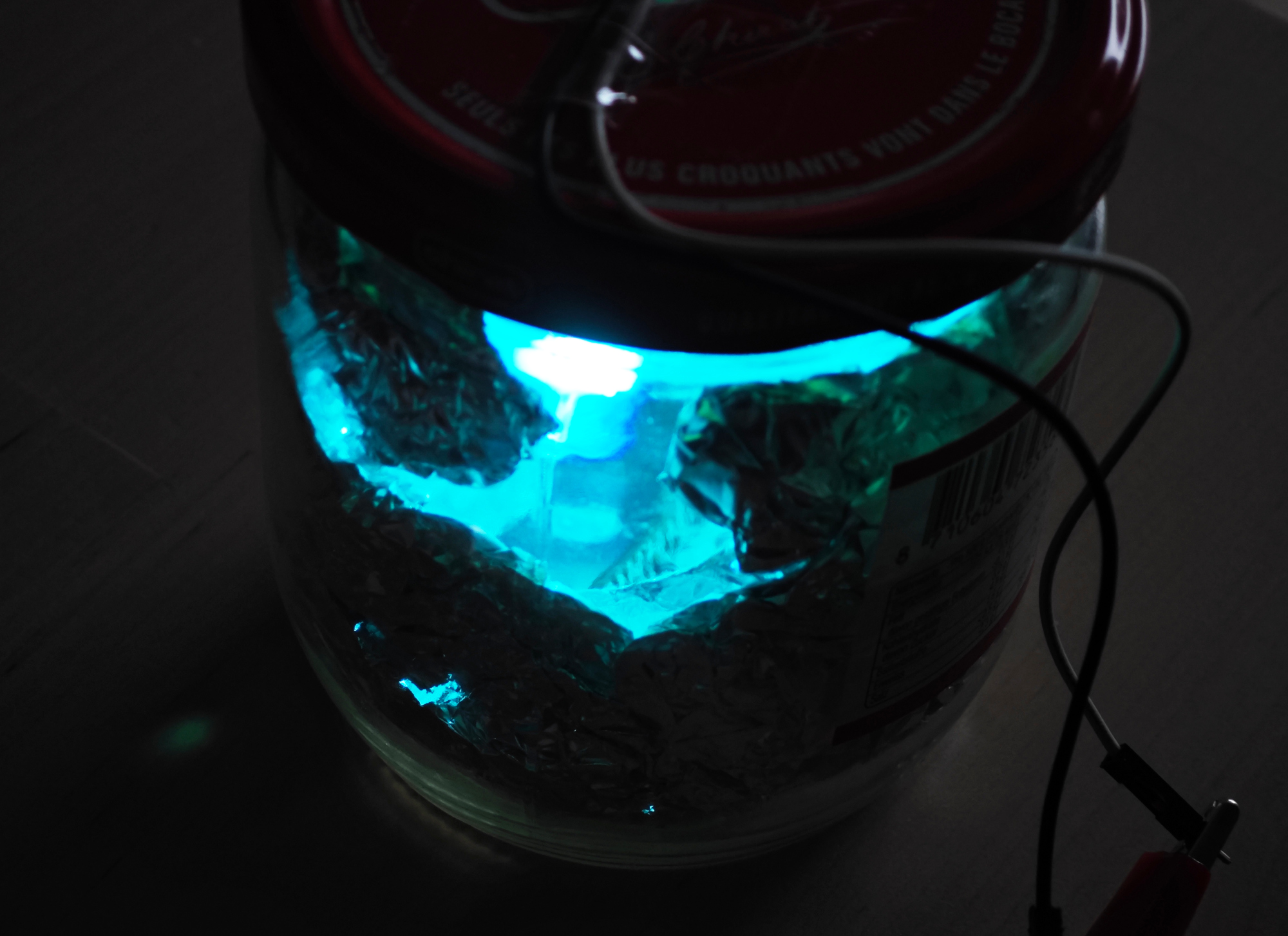
Lamp was mounted in a pickle jar (literally), with majority of walls covered by aluminum foil. Glass was filtering most of <365nm light. This way emission point of the lamp was within ~2cm from the chip, and erasing it took just 10 minutes.
Programming
With MiniPro TL866 it was straightforward (now it can work with open source software).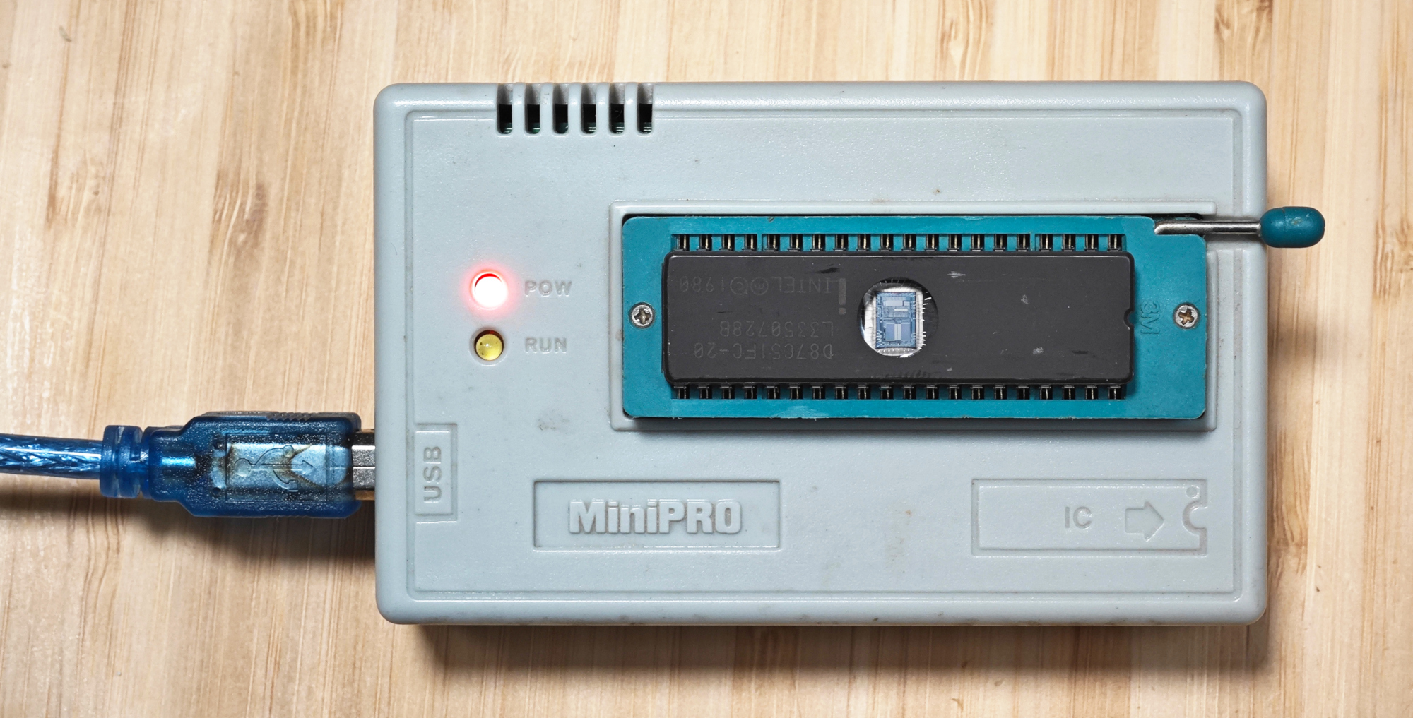
Writing demo program
Enough photos, time to code! In addition to standard blinking LED I decided to calculate some prime numbers and print them via serial port as it's already somewhat challenging task for 44-year old microcontroller. Initially I followed path of Jay Carlson and tried to use modern IDE for 8051-compatible chips from Silicon Labs (Simplicity Studio). Unfortunately, while it works for blinking LED, serial port peripheral apparently is not binary compatible (and it makes sense - serial port in 8051 is very simple by today's standards). So I switched to open source SDCC which worked perfectly.I did not wanted to introduce complexity of doing serial port IO with ring buffer and interrupts, but did slight optimization in 1-byte putchar: It waits for character transmission end before sending next character, not after. This way further compute and serial IO can be partially parallelized. To ensure that it works for first character I set TI = 1 in the beginning of the program (i.e. "transmission of previous character done").
#include <8051.h>
#include <stdio.h>
#include <stdbool.h>

int putchar(int c) {
    /* We never start when transmission is not complete */
    while (TI==0);      /* Wait until stop bit transmit */
    TI = 0;
    SBUF = c;
    return c;
}

void toggle_led(void)
{
    P1_0 = !P1_0;
}

int main (void)
{
    int i, j, loop_limit;
    bool is_prime;

    //Serial port speed. Perfect 9600 for 18.432MHz crystal
    TH1 = (unsigned char)(256-5);//No "overflow in implicit constant conversion"
    TMOD = 0x20;
    SCON = 0x50;
    TR1  = 1;
    TI = 1;//To continue work while we are transmitting - we are waiting before transmission, not after


    printf("Hello world!\r\n");
    printf("Let's calculate some primes: 2");
    while (1)
    {
      for (i = 3; i <= 32000; i+=2) {
          loop_limit = 180;
          if(i-1<loop_limit)loop_limit = i-1;//We will not calculate square root :-)
          is_prime = true;

          for (j = 2; j <= loop_limit; ++j) {
              if (i % j == 0) {
                  is_prime = false;
                  break;
              }
          }

          if (is_prime) {
              toggle_led();
              printf(" %d", i);
          }
      }

      printf("\r\nHere we go again: 2");
    }
}
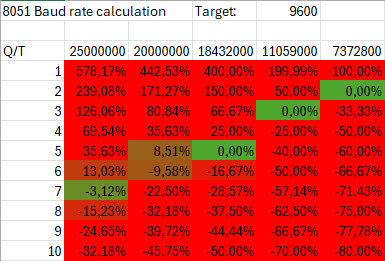
As 8751 had no PLL (not surprisingly), getting proper serial port speed appeared to be most challenging. Serial port speed is defined by quartz frequency and timer1 reload value - TH1. Initially I tried to run it on 20Mhz crystal with TH1=256-5 and was unable to receive correct data on the computer, while oscilloscope was still able to decode it. It appeared that baud rate had 9% error. While it is possible to configure CP2102 for custom baud rate (X = F/(12*32*Y) where F is quartz frequency and Y is timer reload value), another option is to use different quartz crystal for lower error.
Prototype assembly
P1.0 (pin 1): LED.Reset (pin 9): Active high. Pull down with resistor, connect to VCC via capacitor for short reset at power up.
TXD (pin 11): Serial port out.
XTAL1 and XTAL2 (pins 18 and 19): Crystal, 18.432Mhz in my case. Worked without external capacitors, even though it might have some slight frequency error / be less stable. Parasitic capacitance of breadboard is too low (~2pF).
GND (pin 20) and VCC (pin 40): 5V power supply.
EA (pin 31): External memory disable (to use internal EPROM), connect to VCC.
Testing
With correct serial port speed - it works!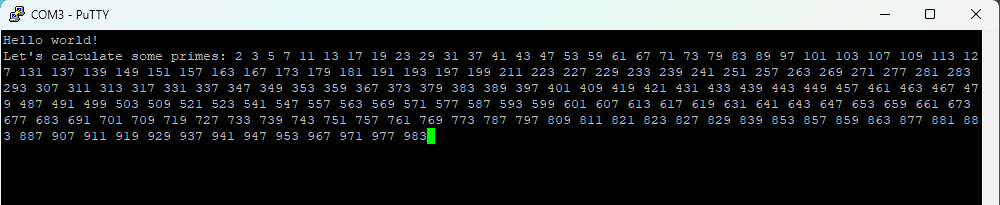
If we look at the TX signal on oscilloscope during printing of different numbers - we can see something interesting:
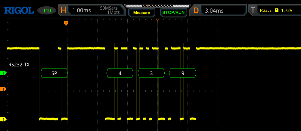
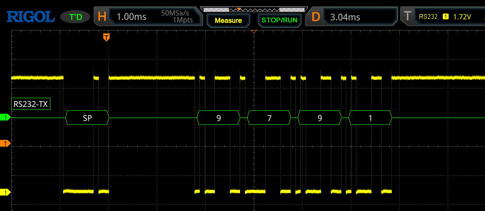
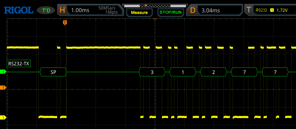
When printing 3-digit numbers - delay between space and first digit is ~1.25ms, 1.8ms for 4 digit and 2.5ms for 5 digit. Why is that?
After printf(" %d", i) prints space, it needs some time to convert integer to string. And it's getting longer for longer numbers. As there is no hardware division of 16-bit integers in 8051 - straightforward implementation of itoa is so slow that you can see the delay even at 9600 baud rate.
Resume
All this took around 6 hours, with ~8 erase-program iterations which were quite slow without devboard in a classical sense. Most necessary features of modern microcontrollers are already present in 87C51 - it is surprising how ahead of it's time it was. Still, there are few things it lacks compared to chips we use today, which could have helped in this test program:1) Raw performance. 1(one) 8-bit MOPS vs ~50-150 32-bit MOPS we can have now for 1-2$. Gap in math is even wider, today we are spoiled by relatively fast hardware division and multiplication. It is not unheard to even have hardware 32-bit floating point math in <5$ chips.
2) PLL. Today with some common/cheapest 8Mhz crystal many useful frequencies can be synthesized, so no need to have large stock of crystals for different applications.
3) On chip debugging and programming allows for very fast iterations.
4) Serial ports with buffers + much faster baud rates are common.
5) Internal reset circuit, brown-out detection, watchdog timer.
So, while 8051-compatible chips are cheaper (often cheapest), development requires more work and consideration. But for high-volume applications where task is relatively simple and does not require a lot of math - it can still be the solution with lowest total cost, and this is why derivatives of 8051 are still in use today (+ some legacy code reuse).


May 12, 2024

 @BarsMonster