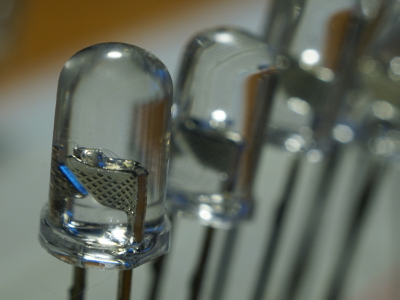
Flickering LED reverse-engineering (+RGB)
 1.5 years ago there was an attempt to reverse engineer behavior of flickering LED as a black box. That time the results were that flickering does not repeat itself (so it's not something like LFSR pseudorandom generator), brightness is set by PWM and there is some distribution of brightness. Since then more results wereachieved, and I also got some time to dig in.
 Previously it was discovered that there are multiple variants of die of flickering LEDs. You may see photos and read some clues on their inner workings here - siliconpr0n.org, cpldcpu.wordpress.com, hackaday.com. It is surprising that seemingly simple task of flickering LED is being solved numerous times by full custom ASIC, and there is even some competition/progress!
Red (candle) flickering LED
 Die size 580x476 µm, 3µm technology.
 This design is apparently using phase difference between 2 RC oscillators as source of random data. There are multiple designs in the wild, some other apparently based on LFSR with single oscillator. There are several variants of this die, some are apparently using LFSR and 1 oscillator. More on the topic: siliconpr0n.org, cpldcpu.wordpress.com, hackaday.com.
After metalization etch:

RGB flicker LED
 Unlike previous LED, this one is completely deterministic: diodes differ slightly only in RC oscillator frequency (~±10%). Regular structure at the lower-left side suggests that it's some sort of microcode-driven design. .
Die size 553x474 µm, 1.5µm technology. Even though logic is more complex die area is actually a bit smaller, thanks to "more advanced" 1500nm technology. I only got decent photo of this chip from the 3rd try, these tiny (~0.25мм²) dies are really stressful to work with: 1, 2.
After metalization etch:

PS. Thanks for these interesting chips to ASIP department of Gomel State University.


 @BarsMonster